Posts

Showing posts from June, 2017

Front Wheel and Rear Wheel Drive

Image
Before buying a car, many thoughts enter your head such as safety features, engine, transmission system, warranties, comfort, reversing sensors and cameras and most importantly the cost. In addition to this, you should also look into the drive wheel i.e whether you want a Front Wheel Drive (FWD) or a Rear Wheel Drive (RWD). The choice you make depends on your driving skills, terrain, weather and the tires used. In a FWD, the power produced by the engine is transferred to the front wheels of the vehicle whereas in a RWD, the power from the engine is transferred to the rear wheels via a drive shaft.  Transverse engines are employed in FWD where the crankshaft axis is perpendicular to the axis of the vehicle. In RWD, longitudinal engines are used where the crankshaft axis is along the length of the vehicle which increases it's weight. Majority of the cars use FWD these days while RWD is used in sports cars. Each wheel drive has it's advantages and disadvanta...

All about Brayton

Image
The thermodynamics behind the functioning of the gas turbines is the Brayton cycle. This cycle consists of four processes which may be closed or open. In a closed cycle, the working fluid is circulated within the system after a complete cycle as in the case of steam turbines. In open cycle, the working fluid enters at the inlet and leaves at the exhaust of the cycle as observed in the cast of turbojets and turbofans. The cycle consists of 2 isobaric (constant pressure) and isentropic (constant entropy) processes. The following processes occur in the gas turbine:    1. Isentropic compression (1-2)    2. Isobaric addition of heat (2-3)    3. Isentropic expansion (3-4)    4. Isobaric removal of heat (4-1) Brayton cycle for P-V and T-s diagrams However, compression and expansion processes do not occur in isentropic manner, increasing the compression ratios is the most effective way to increase the output of Brayton cycle. This fig...

3 spool vs 2 spool

Image
In the Trent 1000, there is 3 spool arrangement of compressors and turbines. This means that there are three sets of compressors and turbines which are connected by three separate shafts. They are the low pressure compressor (LPC) which is the fan and turbine (LPT), Intermediate pressure compressor (IPC) and turbine (IPT) and high pressure compressor (HPC) and turbine (HPT). This is on contrast to the two spool arrangement currently used in many aircrafts where a LPC/LPT and HPC/HPT are used only. All the three shafts are located within each other. The fan positioned at the front of the engine is run by the LPT via a gearbox so that it can operate at optimum speeds. Since the large diameter fan requires a large torque to start rotating, it limits the high speed attained by the LPT due to which its efficiency decreases. Additions of an additional set of compressor and turbine eliminates the influence of this problem but does not eliminate the problem itself! The problem is elim...

Introduction to Trent 1000

Image
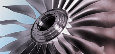
Rolls Royce are one of the leading manufacturers of turbofan engines apart from Pratt & Whitney, General Electric, CFM International and many more. One of their major milestones is the Trent 1000 which is designed and optimised to power the Boeing 787. It is the fifth member of the successful Trent family.   Let's understand certain facts about this turbofan engine before we dig deep into it's systems. It is a three shaft high bypass ratio axial flow British turbofan engine. Occupying a length of 473 cm and diameter of 285 cm, it is one of the most efficient engines discovered by man. It's fan consists of 20 blades made from Titanium alloys with small traces of Vanadium, Iron and Aluminium and is considered one of the lightest in the industry. Presence of chevrons at the rear of the engine helps reduce noise produced due to the temperature differences.      Below are some facts of it that will definitely blow your mind: During take off, tw...

Understanding working of Gas turbine in aircraft

Image

Materials used in Turbine blades

Image
There has been a wide range of materials used for the manufacturing of gas turbine blades. It is one of the most important parts in a gas turbine and any deterioration of it will affect the performance and efficiency of the turbine and most importantly will damage the turbine.  Many materials have been tested and used but the most preferred materials include steel, titanium, Nickel based super alloys and ceramics. The first stage of the compressor is very delicate as it is subjected to a very high temperature of approx. 1400-1500 degree celsius.  This part of the turbine should tolerate high temperatures, high pressures, high thermal stresses including creep and fatigue, vibrations which can influence it's performance. The first stage uses Udimet 500, Nickel based super alloy Inconel 738 or GTD 111.  The relatively cold stages of the turbine employ titanium as there are chances of it igniting when used above 500 degree celsius.      ...